RD 34.40.507 Typical operating instructions for automated deaeration plants for feeding the heating network
MINISTRY OF ENERGY AND ELECTRIFICATION OF THE USSR
MAIN TECHNICAL DEPARTMENT FOR THE OPERATION OF POWER SYSTEMS
STANDARD INSTRUCTIONS
FOR THE OPERATION OF AUTOMATED
DEAERATION INSTALLATIONS
HEATING NETWORK FEEDBACK
TI 34-70-032-84
SOYUZTEKHENERGO
Moscow 1985
DEVELOPED by Sibtechenergo
CONTRACTOR A.M. BRAVIKOV
APPROVED by the Main Technical Directorate for the Operation of Power Systems on July 13, 1984.
Deputy Head D.Ya. SHAMARAKOV
|
TYPICAL OPERATING INSTRUCTIONS FOR AUTOMATED DEAERATION INSTALLATIONS FOR HEATING MAKE-UP |
TI 34-70-032-84 Introduced for the first time |
Expiry date set
until 01.01.95
This Standard Instruction applies to automated deaeration plants with vacuum jet-bubble deaerators and atmospheric deaerators with jet and jet-bubble columns operating at constant average daily hydraulic loads with a uniform distribution of water and steam flows between all parallel operating deaerators, united by group control of the deaeration mode.
The standard instruction establishes the requirements for the operation of deaeration installations for feeding the heating network.
The standard instruction is the basis for the preparation of local instructions and is mandatory for the engineering and technical personnel of power plants and heating and production boiler houses who develop local instructions.
1. GENERAL PROVISIONS
1.1. Deaerators for feeding the heating system are designed to remove corrosive gases - oxygen and free carbon dioxide - from make-up water.
1.2. The deaeration plant consists of:
Non-deaerated water heater;
Deaeration columns-deaerators;
make-up pumps;
booster tank for make-up pumps.
The role of booster tanks, as a rule, is performed by accumulator tanks of heating systems or deaerator tanks of atmospheric deaerators, as well as tanks specially installed for this purpose in some installations with vacuum deaerators;
Means of automatic control, providing automatic maintenance of the mode of deaeration and replenishment of the heating network (application);
Individual for each vacuum deaerator gas suction devices;
Vapor cooler individual for each atmospheric deaerator;
Deaerated water cooler in installations with atmospheric deaerators.
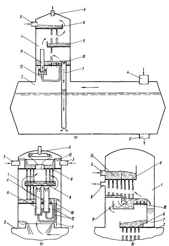
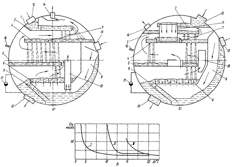
1.3. Technical (design) characteristics of deaerators (Fig. -) are given in Table. .
a- manufactured since 1976; b- issued in the period 1968 - 1976. and reconstructed;
in- experimental data on the dependences of the residual oxygen content in the deaerated
water from water heating in the deaerator;
1 - cylindrical horizontal body; 2 - 5 - perforated jet plates; 6 - bubbling plate;
7 - partitioning threshold; 8 - evaporation compartment; 9 - drainage channel; 10 - steam bypass
valve; 11 - water bypass box; 12 - branch pipe for supplying water for deaeration; 13 - inlet pipe
coolant; 14 - steam outlet pipe; 15 - branch pipe for the removal of deaerated water; 16 and 17 -
sensors for measuring the temperature in the compartment and the water level used when setting up the deaerator;
18 - hole in the partition between the sections of the deaerator DV-800 and DV-1200;
I - for the DV-400 deaerator, produced in the period 1968 - 1976, tested at the Gorky CHPP
car factory; maximum deaerator capacity 500 t/h at non-deaerated temperature
water 30 °C; II - for the DV-800 deaerator, produced in the period 1968 - 1976, tested on
Ust-Kamenogorsk CHPP. Maximum deaerator capacity 800 t/h at temperature
non-deaerated water 30°
C; II - for the DV-400 deaerator, produced after 1976, tested in
heating networks of the city of Kursk
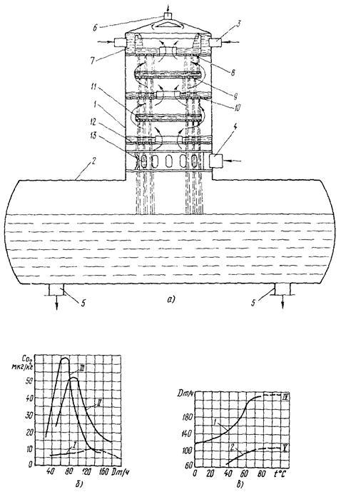
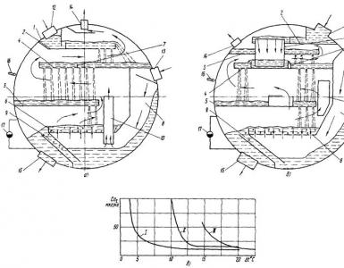
Rice. 2. Atmospheric deaerator with jet column:
a- design of the deaerator; b- dependences of the residual oxygen content in deaerated water
from the water flow to the deaerator for the BKZ column with a capacity of 200 t/h; in- dependencies limit
deaerator performance on the temperature of non-deaerated water entering the deaerator;
1 - deaeration column; 2 - deaerator tank; 3 and 4 - branch pipes for supplying water and steam; 5 and 6 - nozzles
removal of deaerated water and steam-air mixture; 7 - water distribution device;
8 - 12 - jet plates; 13 - steam distribution device; non-deaerated water temperature,
entering the deaerator: I - 97 °С; II - 67 °С and III - 40 °С; IV and V - columns BKZ performance
200 and 100 t/h; - - - - the expected nature of the process
Rice. 3. Atmospheric deaerators with a jet-bubble column with a capacity of:
a- from 50 to 100 t/h; b- from 200 to 300 t/h; in- from 75 to 300 t/h;
1 - deaeration column; 2 - deaerator tank; 3 and 4 - branch pipes for supplying water and steam;
5 and 6 - outlet pipes for deaerated water and steam-air mixture; 7 - spillway water seal;
8 and 9 - jet plates; 10 - bubbling plate; 11 - steam bypass valve;
12 - water filling pipe; 13 - water distribution device
Table 1
|
Vacuum deaerators (Fig. , a and b) |
Atmospheric deaerators with column |
||||||||||||||||||||||||||||||||
|
table 2 The residual content of free carbon dioxide after the deaerator (if it is not completely removed in a normally operating deaerator) is eliminated by alkalization of the make-up water. 1.5. The deaerators for feeding the heating network once a year should be subjected to an internal inspection through removable hatches, and, if necessary, maintenance and cleaning of the deaeration elements. 1.6. Symbols of circuit elements are given in the appendix. 2. SAFETY DEVICES AND SAFETY MEASURES DURING OPERATION OF DEAERATION INSTALLATIONS2.1. Atmospheric deaerators must be tested and technically certified in accordance with the norms of the USSR Gosgortekhnadzor. 2.2. Hydraulic seals are used as protective devices against unacceptable pressure increase and overflow with water in atmospheric and vacuum deaerators. 2.3. The hydraulic seal actuation pressure in atmospheric deaerators is 0.15 MPa (1.5 kgf / cm 2), the maximum allowable pressure in the deaerator during the operation of the hydraulic seal is 0.17 MPa (1.7 kgf / cm 2). 2.4. When draining deaerated water from a vacuum deaerator into an atmospheric pressure tank by gravity, the installation of protective hydraulic seals is not required, since the drain pipeline acts as a protective seal. In this case, shut-off and control valves on the drain pipeline should be absent. 2.5. Atmospheric and vacuum deaerators before being put into operation after installation and repair associated with the restoration of the density of the deaerator, and also, as necessary, must be subjected to a hydraulic test with an overpressure of 0.2 MPa (2.0 kgf / cm 2), but at least every 8 years. 2.6. The booster tanks must be equipped with an overflow pipe for overflow protection and pressure equalization inside and outside the tank. The capacity of the overflow pipe must be at least the capacity of all pipes supplying water to the tank. The cross section of the vent pipe for tanks of atmospheric pressure must ensure free entry into the tank and free release from the tank of air, excluding the formation of a vacuum when pumping water from the tank and an increase in pressure above atmospheric pressure when filling the tank. 2.7. Accumulator tanks must have anti-corrosion protection, which can be carried out using: Sealing liquid AG-4 (sealant); Various coatings of the inner surface of the tanks; cathodic protection. 2.8. The condition of the storage tanks and their suitability for further operation are determined annually in accordance with the emergency circular No. Ts-08-82 (T) “On the prevention of sudden destruction of metal hot water storage tanks” (M .: SPO Soyuztekhenergo, 1984). 3. DEAERATION INSTALLATIONS WITH VACUUM DEAERATORS (Fig. -)3.1. Features of thermal schemes of deaeration plants
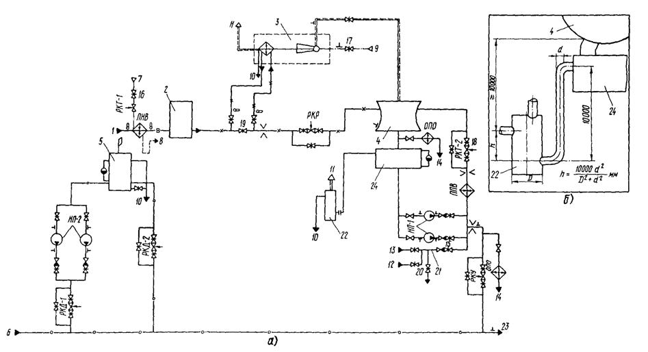
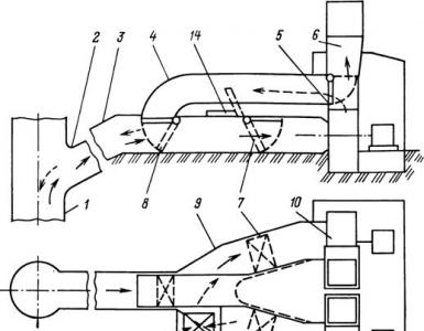
Rice. 6. Scheme of a deaeration plant with a vacuum deaerator, a vacuum booster tank and an external storage tank ( a) and a protective water seal ( b). 3.2.4. Submit an application for the assembly of electrical power circuits for electric drives of shut-off and control valves, instrumentation and pumps. 3.2.5. Submit an application for preparation for the operation of a water treatment plant. 3.2.8. Prepare the non-deaerated water heater for operation; assemble circuits for removing condensate, heating steam and non-condensable gases from the heater. For the scheme of Fig. prepare the hot water heater for operation. a) open the valve on the cooling water in front of the ejector; b) by opening the control valve RKR on non-deaerated water, supply cooling water through the ejector in the amount of 100 - 160 t/h; c) by smoothly opening the valve 17 on the steam line in front of the ejector, within 10 - 15 minutes, raise the pressure in front of the ejector nozzles to a nominal value of 0.60 MPa (6.0 kgf / cm 2); d) create a vacuum in the deaerator of 95 - 97%. 3.3.3. Switch on the NVD non-deaerated water heater; for this, it is necessary: a) open the valve 16 on the steam supply to the NVD, while it is necessary to monitor the water temperature at the outlet of the heater, which should not exceed 35 °C (according to the operating conditions of the water treatment plant); b) increase the water temperature at the outlet of the heater to 30 - 35 °C by remotely opening the control valve RKT-1 at the steam supply to the heater; c) run the heater; d) in case of insufficient water heating, check the circuit for removing non-condensable gases, and when the level rises to the maximum allowable value, check the circuit for draining condensate; e) check the operation of the non-deaerated water temperature controller, for which, remotely closing the RKT-1 control valve, lower the water temperature at the outlet of the heater to the minimum allowable value, then switch the controller to automatic operation, after which the control valve should begin to open. Similarly, check the operation of the automatic regulator at the maximum allowable temperature. 3.3.8. By controlling the pressure on the suction side of the network pumps, smoothly increase the flow of non-deaerated water into the deaerator to the average daily value by simultaneously opening the control valve PKR on non-deaerated water and valve 19. The automatic control system must maintain the adjustable parameters within the specified range. Notes: 1. When starting the unit (see Fig. ) with an empty storage tank, the NP make-up pump should be switched on only after the water level in the storage tank rises above the minimum allowable value by 1.0 m, after which superheated water is supplied to the deaerator . 2. The inclusion of the second deaerator into parallel operation (settings in Fig. and) is carried out similarly to the inclusion of the first deaerator in accordance with paragraphs. , , - . 3.4. Deaeration plant maintenancea) regularly, at least twice per shift, bypass the equipment of the deaeration plant, record in the operational log all operations carried out with the equipment; record the main parameters of the operating mode of the deaeration plant in the daily record; b) monitor the normal operation of control and measuring devices, automation equipment; c) if deviations are found in the readings of instrumentation from the required values, it is necessary to find out the cause and take measures to eliminate them; d) make an entry in the defect log about malfunctions in the operation of the deaeration unit, the elimination of which by the forces of the watch personnel is impossible; e) carry out shift testing of the electrical circuit of the alarm system and make appropriate entries in the operational log; f) monitor the normal operation of the make-up pumps, regularly replenishing the bearing grease, monitor the vibration of the electric motor and the pump, and eliminate increased water leakage through the pump shaft seals. Periodically alternate in operation the standby and working pumps. Testing in operation of devices for automatically switching on the reserve of the pump (AVR), as well as alternating pumps in operation, to be carried out according to the schedule available at the CHPP; g) periodically blow out water-gauge glasses; h) periodically (once every two weeks) check the serviceability of the emergency make-up jumper 21 by moving the valves; i) at least twice a shift, determine the content of oxygen and free carbon dioxide in the make-up water on the discharge side of the make-up pumps after the emergency make-up jumper. For deaeration plants that have not passed the tests, it is recommended to keep the controlled parameters within the specified range: The temperature of non-deaerated water entering the deaerators is 30 - 35 °C, while the deaerator performance is close to the nominal one. With an increase in the temperature of non-deaerated water, the performance of the deaerator increases, but not more than up to 120% of the nominal capacity. With a decrease in the temperature of non-deaerated water, the productivity decreases; The pressure in the deaerator is 0.0075 - 0.06 MPa (0.075 - 0.5 kgf / cm 2); Water heating in the deaerator 15 - 25 °С. The maximum heating of water in the deaerator at a capacity less than the nominal value exceeds 25 °C; The temperature of the heating medium (superheated water) within 65 - 120 °C; The pressure on the discharge side of the charging pump is at least 95% of the nominal value (pump overload mode). At a pressure of less than 98%, turn on the standby pump; The steam pressure in front of the ejector nozzles is 0.5 - 0.7 MPa (5.0 - 7.0 kgf / cm 2). Heating of the cooling water in the EP-3-25/75 ejector should be 5 - 10 °C. It is not recommended to work outside the specified heating range, since at lower heating, erosive wear of the ejector tubes occurs due to high water velocities in the tubes, and at a higher temperature, the ejector is steamed. 3.5. Shutdown of the deaeration plant3.5.1. Before a planned shutdown of the deaeration plant, it is necessary to accumulate a supply of deaerated water - the full available volume of storage tanks. 3.5.2. After receiving the order for the upcoming shutdown, prepare the jumper for emergency make-up 21 for operation; Close control valve 20; Open valve 15. 3.5.3. For heating networks with remote storage tanks (see fig. and ), warn the personnel servicing the make-up unit from the storage tanks about the upcoming increase in water consumption for make-up from the storage tanks. 3.5.4. By smoothly closing the control valve, reduce the flow of non-deaerated water to the deaerators to 30% of the nominal capacity. In this case, the automatic control system must maintain the adjustable parameters within the specified limits. If the pressure in the return manifold of the heating system drops below the permissible level and it is impossible to increase the pressure by increasing the flow of water from the storage tanks, supply chemically purified non-deaerated water to the heating network through the emergency recharge jumper. 3.5.5. Turn off the deaerator for overheated water, to do this, in the diagrams (see Fig. and), close the control valve RKT-2 and valve 18 on superheated water, and in the diagram (see Fig.), turn off the PPV heater for steam and then for water. 3.5.6. Disconnect the steam ejector by closing the valve 17 on the steam supply to the ejector. 3.5.7. Turn off the deaerator for non-deaerated water by closing: Control valve RKR; Valves in front of the ejector and in addition to the ejector on non-deaerated water. If, as a result of the operations performed, the maintenance personnel fail to find out the reason for the increase in the oxygen content in the deaerated water, then further adjustment should be carried out by specially trained personnel in accordance with the recommendations of the appendix. 3.6.13. In the event of hydraulic shocks, it is necessary to stop the supply of superheated water to the deaerator by closing the control valve RKT-2 on the superheated water pipeline. The reason for the occurrence of hydraulic shocks in a working deaerator, as a rule, is the underheating of water in the deaerator to saturation temperature, i.e. increasing the pressure in the deaerator without increasing the temperature of the deaerated water. After closing the control valve RKT-2, the personnel must find out the reason for the increase in pressure in the deaerator, to do this, check: a) operating mode of the ejector (steam pressure in front of the ejector and heating of the cooling water in the ejector are set in accordance with paragraph ); b) absence of air suction in the vacuum system (close the valves on the drainage, water-gauge glasses, etc.); c) operation of the ejector "on itself", to do this, after turning off the deaerator for overheated water (by closing the control valve RKT-2 and valve 18), close the valve on the suction line from the deaerator. A serviceable ejector, when working "on itself" at a steam pressure in front of the ejector nozzles of 0.5 - 0.6 MPa (5.0 - 6.0 kgf / cm 2) or more, should create a vacuum of 96 - 91%. If the ejector does not create the specified vacuum, then it is necessary to check the filling of the ejector hydraulic seals with water, to do this, turn off the ejector for steam and then, after increasing the pressure in the ejector suction pipe to atmospheric pressure, gradually increase the steam pressure in front of the ejector nozzles to 0.5 - 0 for 15 minutes, 6 MPa (5.0 - 6.0 kgf / cm 2), while the hydraulic seals are filled with water. If, after filling the water seals with water, the ejector does not create the required vacuum, then it is faulty and it is necessary to open it to identify the fault. 3.6.14. When water comes out of the signal water seal 7 (Fig. ) and water is ejected from the exhaust pipe 3, check the water entrainment by the exhaust gases from the deaerator. To prevent entrainment, close the valve on the suction line from the deaerator by 85 - 95%. If at the same time the ejection of water from the ejector stops, then during the operation of the deaerator, the valve on the suction line should not be opened completely, but only until the pressure in the deaerator and on the suction side of the ejector is equalized.
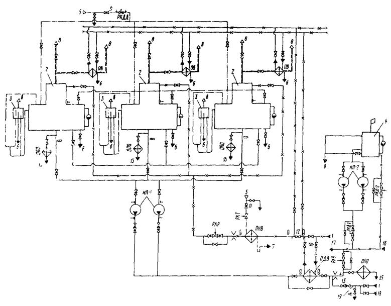
Rice. 7. Three-stage steam jet ejector EP-3-25/75: a- layout of nozzles; b- Dependence of (absolute) suction pressure on flow If, when water is ejected from the exhaust pipe, the pressure on the suction side of the ejector is less than the pressure in the deaerator above the bubbling tray by 0.02 MPa (0.2 kgf / cm 2), then it follows that the deaerator is filled with water and water from deaerator enters the ejector. The reasons for filling the deaerator with water are given in the appendix. 4. DEAERATION PLANT WITH ATMOSPHERIC DEAERATORS (Fig. )
Rice. 8. Scheme of a deaeration plant with atmospheric deaerators: 1 - from a water treatment plant; 2 - deaeration column with deaerator tank; 3 - protective water seal; 4 - storage tank; 4.1.2. Check the closing of the valves on the pipelines: Non-deaerated water supply in front of the deaerated water cooler (valve 10); Emptying deaerator tanks; Steam supply to the deaerators (valve 9) and to the non-deaerated water heater (valve 11); Injection of make-up pumps NP-1; Bypass of deaerated and non-deaerated water in addition to the deaerated water cooler; Water bypass in addition to adjustable valves RKR and RKU. 4.1.3. Check the closing of the valves on the drains of the steam pipelines in front of the valves 9 and 11. 4.1.4. Close all control valves that are not in operation. 4.1.5. Open the valves on the evaporator pipelines to the atmosphere of all deaerators. 4.1.6. Open valve 12 by 30% on non-deaerated water in addition to vapor coolers. 4.1.7. Check the opening of valves on pipelines: Vapor supply to the vapor coolers of all deaerators; Cooling water before and after the vapor coolers; Equalization for steam and water; Supply of non-deaerated water in front of each deaerator; Discharge of deaerated water from deaerators; Steam supply in front of each deaerator; Before and after the RKR and RKU control valves; Deaerated water before and after EFA; Non-deaerated water before and after EFA; Suction feed pumps. 4.2. Starting the deaeration plant (when heating networks are fed during the start-up period from storage tanks)4.2.1. Turn on the pressure regulator in the deaerators, after which the RKD valve should open. 4.2.2. Warm up the steam line for supplying steam to the deaerators up to valve 9 by opening the drain valve in front of the valve. 4.2.3. Warm up the deaerators by gently opening valve 9. After opening valve 9, close the drain valve in front of it. When the pressure in the deaerators rises to 0.125 MPa (1.25 kgf / cm 2), the RKDD valve should automatically close. In the event of an increase in pressure in the deaerators of more than 0.125 MPa (1.25 kgf / cm 2), stop opening the valve 9, if the pressure increase does not stop, then partially close the valve 9. 4.2.4. Open valve 10 on non-deaerated water in front of the EFA. When filling the deaerator tanks to 0.5 of the maximum allowable level, turn on the make-up pump NP-1. After checking the operation of the pump, open the valve on the discharge side of the pump. Note. When starting the deaeration plant with filled deaerator tanks (when the water level in the tanks is more than 0.5 of the maximum allowable level), before supplying non-deaerated water to the deaerators, the make-up pump NP-1 should be put into operation. 4.2.5. Supply non-deaerated water (not more than 30% of the nominal capacity) to the deaerators by opening the control valve PKR, after which valve 9 on the steam supply to the deaerators is fully opened (if it was not fully open). 4.2.6. Check the operation of the automatic water level regulator in the deaerator tanks. To do this, by opening the RKU control valve at the heating network feed, lower the water level in the deaerator tanks to the minimum allowable value (at the same time, the pressure on the suction side of the network pumps should be controlled). Then set the level regulator to automatic operation, after which the RKU control valve should automatically close. Similarly, check the operation of the level regulator at the maximum allowable level in the tanks. 4.2.7. Switch on the NVD non-deaerated water heater; for this, it is necessary: a) warm up the steam line for supplying steam to the NVD up to valve 10 by opening the drain valve in front of the valve; b) open valve 10 on the steam supply to the NVD, then close the drain valve in front of the valve; c) by remotely opening the RKT valve, increase the temperature at the outlet of the NVG heater to the value required in the paragraph; d) check the operation of the heater. In case of insufficient heating of water in the heater, check the circuit for removing non-condensable gases, and when the level rises to the maximum allowable value, check the circuit for draining condensate. 4.2.8. Check the operation of the non-deaerated water temperature regulator; to do this, by closing the control valve RKT on the steam supply to the heater, lower the water temperature at the outlet of the heater for deaerators (see Fig. ) to 94 °C, and for deaerators (see Fig. ) to 89 °C. Then switch the regulator to automatic operation, after which the control valve should begin to close. Similarly, check the operation of the automatic regulator at the maximum allowable temperature. 4.2.9. Close the valves on the exhaust gas to the atmosphere of all deaerators. 4.2.10. Gradually increase the flow of non-deaerated water to the deaerators to the average daily value by opening the control valve PKR, monitoring the pressure on the suction side of the network pumps. In this case, the means of automatic control must maintain the adjustable parameters within the specified limits. 4.2.11. In the steady state (1 hour after start-up), determine the content of oxygen and free carbon dioxide in the make-up water on the discharge side of the make-up pumps NP-1. 4.3. Connecting one deaerator to deaerators operating in parallel4.3.1. Make sure to comply with - , and . 4.3.2. Submit an application for inclusion in the work of the CIP. 4.3.3. Check that the valve on the deaerator tank emptying line is closed. 4.3.4. Open the exhaust valve to the atmosphere. 4.3.5. Check the opening of the valve on the vaporizer to the vaporizer cooler. 4.3.6. Turn on the vapor cooler for the cooling water by opening the valves before and after the vapor cooler. 4.3.7. Supply steam to the deaerator by opening the valve on the steam supply to the deaerator. 4.3.8. Open the valve on the equalizing steam line. 4.3.9. Supply water to the deaerator by opening the valve on non-deaerated water in front of the deaerator by 20 - 30%. Note. When connecting a deaerator with a filled deaerator tank to deaerators operating in parallel, before supplying non-deaerated water to the deaerator, open the valves on the equalizing water pipeline and on the outlet of deaerated water from the deaerator. 4.3.10. When equalizing the water level with other deaerators, open the valve on the equalizing water pipeline. 4.3.11. Open the valve on the outlet of deaerated water from the deaerator. 4.3.12. Fully open the valve on the supply of non-deaerated water to the deaerator. 4.3.13. Close the exhaust valve to the atmosphere. 4.4. Deaeration plant maintenance4.4.1. When servicing the deaeration unit, one should be guided by paragraphs. and . e) the water level in the deaerator tanks must be maintained at the middle of the maximum allowable value of ±0.5 m; e) the flow rate of cooling water through the vapor coolers should be equal to the design value. In the absence of a flow meter, the calculated flow rate of cooling water is determined approximately by the pressure drop at the water inlet to the vaporizer cooler and outlet from it in accordance with the nameplate data of the vaporizer cooler. 4.5. Shutdown of one deaerator with deaerators operating in parallel4.5.1. Set the flow of non-deaerated water to the deaerators in accordance with the performance of the deaerators remaining in operation by covering the control valve RKR. 4.5.2. Close the valves on the pipelines in front of the deaerator in the following sequence: On non-deaerated water; On the supply of steam to the deaerator; At the outlet from the deaerated water deaerator; On the equalizing pipeline by water; On the equalizing pipeline for steam; On the cooling water before and after the vapor cooler. 4.5.3. Empty the tank (if necessary) by opening the valve on the drain line. 4.6. Shutdown of the deaeration plant4.6.1. Before a planned shutdown of the deaeration plant, create a supply of deaerated water by filling the storage tanks. 4.6.2. After receiving the order for the forthcoming shutdown, prepare the jumper for emergency make-up 19 for operation; close control valve 14; open valve 13. 4.6.3. Warn personnel servicing the recharge unit from storage tanks about the upcoming increase in water consumption from storage tanks. 4.6.4. Smoothly, following the pressure in the suction manifold of the network pumps, reduce the flow of non-deaerated water to the deaerators to 15 - 20% of the nominal capacity by covering the control valve RKR. In this case, the automatic control system must withstand the adjustable parameters within the specified limits. When the pressure in the suction manifold drops below the permissible level and it is impossible to increase the pressure by increasing the flow of water from the storage tanks, supply chemically purified non-deaerated water to the heating network through jumper 19. With an increase in pressure in the deaerators of more than 0.125 MPa (1.25 kgf / cm 2), stop unloading the deaerators by water, if necessary, increase the flow of non-deaerated water into the deaerators to restore pressure in the deaerators. 4.6.5. Switch off the non-deaerated water heater by steam. 4.6.6. Disconnect the deaerators by steam by closing the control RKD-1 and valve 9 on the steam supply to the deaerators. 4.6.7. Turn off the water deaerators by closing the control valve RKR at the supply of non-deaerated water to the deaerators and valve 10 in front of the deaerated water cooler. 4.6.8. Stop booster pump. 4.6.9. Close the valves on the discharge side of the make-up pumps. 4.6.10. If necessary, empty the deaerator tanks by opening the valves on the tank emptying pipelines. 4.7. Actions of personnel in case of violation of the regime and malfunctions in the serviced equipment4.7.1. The most dangerous violations of the operation mode of the deaeration plant are: Excess of admissible pressure in deaerators; Overflow of deaerator tanks with water. 4.7.6. In case of violation of the normal operation of the deaeration unit, the maintenance personnel must restore the controlled parameters in accordance with the required values according to p. In doing so, one should be guided by paragraphs. , , - . 4.7.7. When the pressure in the deaerators rises above 0.125 MPa (1.25 kgf / cm 2), by covering the control valve RKDD, reduce the pressure in the deaerators to 0.120 MPa (1.20 kgf / cm 2). If necessary, close the valve 9 (see Fig. ). 4.7.8. When the maximum allowable water level in the deaerator tanks is reached, by covering the control valve RKR, lower the level to the nominal value. If necessary, to lower the level, close the valve behind the PKR valve. 4.7.9. With a rapid increase in the level in the deaerator tanks (for example, when all pumps for feeding the heating network are stopped), reduce the flow of non-deaerated water to the deaerators, while controlling the pressure in the deaerators. With an increase in pressure in the deaerators of more than 0.125 MPa (1.25 kgf / cm 2), maintain the achieved flow rate of non-deaerated water, and after restoring pressure, close the RKDD valve and, if necessary, the valve in front of it. Then close the RKR valve and the valve in front of it. 4.7.10. If water is released through the vent of the vapor cooler, the cause that caused it should be determined. Water release can occur due to: Large entrainment of moisture from the vapor column, accompanied by hydraulic shocks in the vapor pipeline. To prevent moisture carryover, it is necessary to reduce the flow of cooling water through the evaporative coolers by slightly opening the valve in addition to the evaporative coolers. Then (after 1 hour) check the content of oxygen and free carbon dioxide in the make-up water; Clogging of the evaporator cooler drain pipe. A sign of pipeline clogging is a decrease in the temperature of the drainage (from 100 ° C) to the temperature of the outside air; Violations of the density of the evaporator cooler pipe system. To determine the leakage, close the valve on the vaporizer in front of the vaporizer cooler. The presence of water blowing through the vent or water exiting through the drain pipe indicates a leak in the evaporator cooler piping system. Appendix 11. The following parameters are automatically adjusted in the deaeration unit: Non-deaerated water temperature (before atmospheric deaerators and before the water treatment plant for deaeration plants with vacuum deaerators); Pressure in atmospheric deaerators; The temperature of the deaerated water at the outlet of the vacuum deaerator; The water level in the booster tank, if the booster tank is not an accumulator tank; Pressure in the suction manifold of network pumps. 2. The light and sound alarm notifies about the limit values of the deaeration plant modes when: Increasing and decreasing pressure in the suction manifold of network pumps; Decrease in pressure on the discharge side of make-up pumps; Raising and lowering the water level in the booster tank; Increasing the water temperature in front of the water treatment plant (for vacuum deaerators); Increasing and decreasing pressure in atmospheric deaerators. 3. Make-up pumps must be equipped with an ATS system, which is activated when the electric motor of the operating pump is turned off. Make-up pumps designed to operate in variable modes (as a rule, pumps supplying make-up water from accumulator tanks) must additionally be equipped with an ATS system, which is triggered by a decrease in pressure on the discharge side of the operating make-up pump. Appendix 2Vacuum deaerators, produced in the period 1968 - 1976, have a performance less than the design one. To bring the performance of the deaerator to the design value, the deaerator should be reconstructed according to the developments of Sibtechenergo (see Fig. , b). Reconstruction requires: Dismantle the steam bypass box in the bubbling tray; plug the hole from the box with a reamed sheet with the same degree of perforation as the bubbling tray; the box in the plate 5 is drowned out by 50%; Double the hole area in the bubbling tray by drilling new holes; In the DV-800 and DV-1200 deaerators, cut an equalizing hole with an area of 0.15 m 2 in the intersection partition. Appendix 3
| |||||||||||||||||||||||||||||||||