Calculation of the cost of electricity transmission. Determination of network efficiency
Maximum network efficiency.
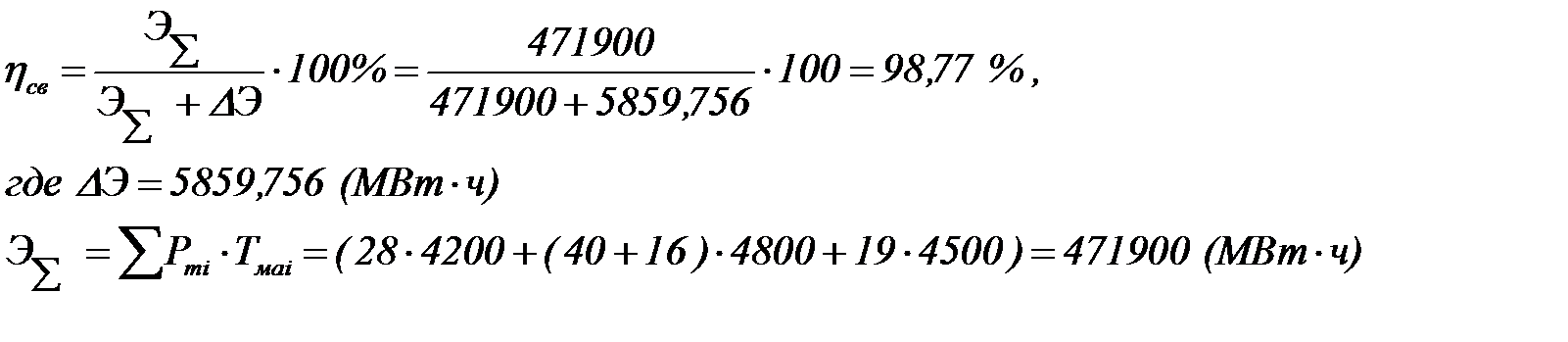
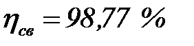
Weighted average network efficiency:
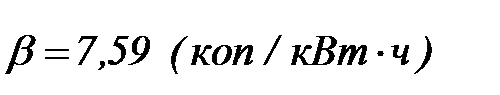
Determination of the cost of transmission and distribution of 1 kWh of electricity:
Conclusion
As a result of the course work in accordance with the task, the optimal version of the electrical network of the load area was developed. For comparison, out of several network configuration options, two were selected based on the lowest cost, highest reliability, and ease of use. In the course of further development of options and calculation of their economic efficiency using the discounted cost method, a variant of the ring network scheme was chosen.
The designed network belongs to the number of regional networks with a voltage of 220 - 110 kV. The network feeds three substations, which include consumers of categories I, II, III in terms of power supply reliability.
Consumers are fed through two transformers at each substation. Transformers are selected taking into account the overload capacity:
At PS-1 - TRDN - 25000/110/10;
At PS-2 - ATDCTN - 125000/220/110/10;
At PS-3 - TDN - 16000/110/10.
Power lines with a voltage of 110 kV are made on reinforced concrete poles, lines with a voltage of 220 kV - on steel poles, in both cases steel-aluminum wires are used. The cross section of the wires is selected according to the economic section, with a check for the allowable overload current in emergency mode. Depending on the type of substation and the number of connections on the high voltage side, the electrical connection diagrams of the switchgear of substations were selected:
On the side of 220 kV SS-2 - a quadrilateral scheme;
On the 110 kV side of SS-2 there is one working busbar system, sectioned according to the number of pipes, with the connection of transformers through a fork of two circuit breakers;
On the side of 110 kV PS-1, PS-3 - a bridge with a switch in the transformer circuits and a repair jumper from the side of the transformers;
On the 10 kV side - PS-2, PS-3 - one single busbar system partitioned by a circuit breaker;
On the side of 10 kV - PS-1 - two single busbar systems partitioned by a circuit breaker;
The quality of electricity in normal and post-emergency conditions is ensured by regulation under load for all transformers. To regulate the voltage on the 10 kV SS-2 buses, adjusting transformers of the LTDN-40000/10 type were used.
The steady regimes were studied and analyzed using the Energy program.
Technical and economic calculations gave the following indicators of the network:
1. Total capital investments of the network:
2. Equipment operating costs:
3. Power and energy losses in the network:
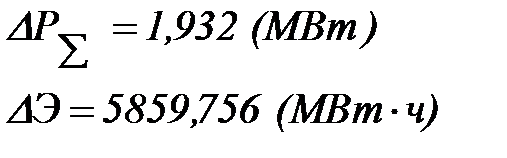
4. Cost of power transmission:
5. Maximum network efficiency:

6. Weighted average efficiency:
Based on the fact that the selected variant of the electrical network satisfies the requirements imposed on it, we consider it optimal.
Bibliography:
1. Reference book on the design of electrical networks / ed. D.L. Faibisovich. - 4th ed., revised. and additional – M.: ENAS, 2012.-376 p.: ill.
2. Rules for the installation of electrical installations./Coll.aut.-M.: Alvis Publishing House, 2012.-816 p.
3. MU No. 128 - Selection of power transformers for substations of power systems and industrial enterprises, taking into account permissible loads / D.A. Polkoshnikov, M.I. Sokolov. - Ivanovo: ISPU, 2009.-24 p.
4. Bushueva O.A., Kuleshov A.I. The electrical network of the load area - a textbook for the course project / ISPU. - Ivanovo, 2006. – 72 p.