Steam boiler DKVR 4-13: description, specifications and instructions
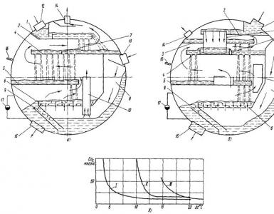
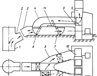
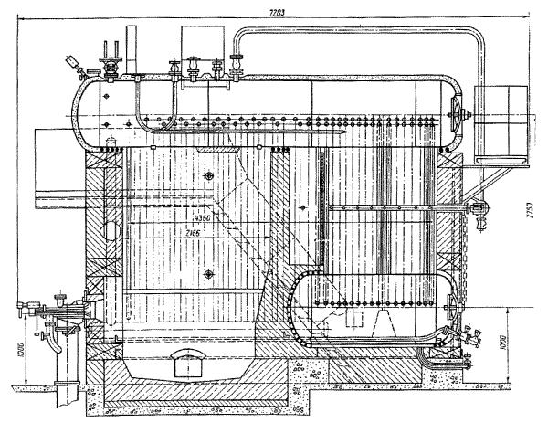
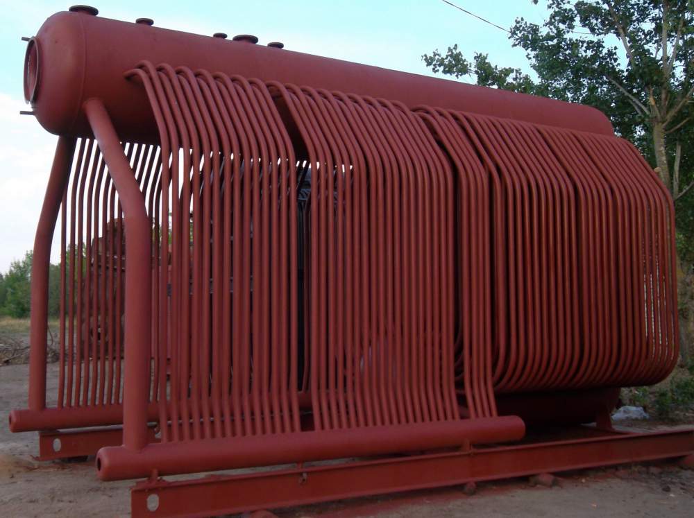
The steam boiler DKVR 4-13, the device of which is discussed below, is a vertical water-tube structure with a furnace screen and a boiler unit. The system itself is equipped according to the type of structural diagram shown in the main photo. A feature of this configuration is the lateral placement of the convective block of the device relative to the combustion compartment. The device kit includes the unit itself, work platforms and stairs, burners, an economizer, a fan, a smoke exhaust device, water-indicating sensors, fittings.
Device
The steam plant under consideration consists of two main ones - the lower and upper drums, as well as a screen-type furnace compartment. The furnace is divided by a brick partition into two chambers (the working part and the residual element). This design allows to increase the efficiency of the steam boiler DKVR 4-13 by reducing the chemical underburning. Gases from the combustion chamber enter the working compartment at the inlet and outlet in an asymmetric manner.
In modifications with steam superheaters, the last elements are installed in the first flue part on the left side of the boiler. The sides of the upper drum receive cooling from the flow of the steam-water composition supplied from the pipes of the front compartment of the convective unit and side screens.
Additional details
The device of the boiler DKVR 4-13 includes safety valves, the main steam valve, a gate valve, taps for sampling the mixture and sampling it for its own blowing needs. These elements are located on the upper main surface of the drum.
The feed pipe is located in the water space of the elongated tank, and the separation mechanisms are located in the steam compartment. In the lower main block there is a fitting for draining water, a perforated tube for purging the system. The liquid level is monitored through a pair of pointers. Two fittings are provided on the front bottom of the upper drum, which serve to select pulses of the amount of water.
Partitions and pipes
DKVR 4-13 downcomer and steam outlet pipes are connected to collectors and drum fittings by welding. To prevent sludge from getting into them when the screens are fed, the ends of the elements are led into the upper compartment of the drum.
The chamber of the afterburning system is separated from the beam by a fireclay partition, which is supported by a cast-iron support mounted on the lower drum. The wall between the first and second flue is assembled using bolts from separate plates. It is first necessary to coat the joints with a special putty or lay an asbestos cord impregnated with liquid glass. The baffle has a hole for laying the branch pipe of the stationary type blowing mechanism. The gas outlet is located on the rear wall. The boiler DKVR 4-13 in a heavy lining is equipped with a light strapping frame. On devices with a design pressure of 1.3 MPa, the superheated steam temperature parameter is not corrected.
Work platforms
These elements are located in places used for servicing the headset and fittings of the unit. Among them:
- Side platform for checking water-indicating devices.
- Similar surface for maintenance of shut-off valves and safety valves of the drum.
- The platform on the back serves for access to the upper drum of the DKVR 4-13 boiler during repairs.
Ladders lead to the sidewalls, and a vertical ladder leads to the rear pedestal.

Other equipment
The DKVR 4-13 unit is equipped with a desuperheater located in the lower drum. It has a drain cock on the steam connection lines. Adjustment of the amount of the incoming mixture is carried out by a jumper. A special valve is placed between the reverse and direct element.
Access to the combustion compartment is provided by a manhole. Depending on the configuration of the device, skimming hatches are provided for fuel skimming near the sidewalls. A pair of such elements is mounted on the side walls at the bottom of the afterburner. There are also windows on the sides of the boilers for cleaning convective pipelines by means of blowing.
Control and adjustment devices
The state of the lower part of the insulation of the upper drum in the combustion chamber is monitored through a hatch at the point of discharge of the tubes of the side screen, from the bottom of the flue on the left side of the unit.
In the lower part from the same end of the DKVR 4-13 boiler, the characteristics of which we will consider below, manholes are installed that serve as windows for regular removal of ash, inspection of the working unit and return ejectors of entrainment. Through similar hatches, the condition of the insulation of the upper drum element is monitored.
The transfer of the structure to the water-heating mode makes it possible to increase the productivity of the installations, reduce the costs for own needs associated with the use of heat exchangers, feed pumps, and continuous blowers. In addition, the cost of water preparation is reduced, fuel is saved.
As the technical characteristics of DKVR 4-13 show, the average operating efficiency of water-heating units increases by 2.5 percent.
Complete set and delivery
The installations under consideration are equipped with fans and smoke exhausters of the VDN and DN types. The package also includes block water treatment devices, filter elements for softening and clarifying water (FOF and FiPA). In addition, the structure is equipped with thermal deaerators, heat exchangers, pumps, and automation kits.
DKVR 4-13 is supplied in bulk, block parts or fully assembled. Reinforcement and some individual components are presented separately. This is due to the impossibility of their transportation in full assembly.
Technical characteristics of the boiler DKVR 4-13
The main installation options are listed below:
Design features
According to the characteristics of the boiler DKVR 4-13, it uses a single-stage evaporative system. The pipes of the side screens are fixed by rolling with one side in the upper drum, and the other ends are welded to the lower chambers.
Longitudinally placed drums are aggregated among themselves through bent boiler elements forming a developed convective beam. The combustion compartment is divided by a fireclay partition, located in front of the convection unit. The first row of pipes is the rear screen of the afterburner compartment. If there are superheaters that are installed in the first flue after the 2nd or 3rd row of boiler nozzles, some elements of the convective bundle are not installed.
The working fluid flows simultaneously into the pipes of the side screens, increasing the reliability of the unit and reducing the water level, as well as sludge deposits in the upper drum.
The separation device of the DKVR boilers consists of a box with a perforated sheet. It serves as a device for maintaining the salinity of the working fluid within 3000 mg / l, if there are no increased requirements for steam.
Exploitation
At the DKVR boiler, the shutters of the drum manholes are located on the rear bottoms. The average liquid level is distributed along the axis of the element. To observe this indicator, a pair of pointing devices on the upper drum serves.
The superheating elements located in the first outlet along the gas flow are unified according to the profile for installations with the same pressure parameter and differ from analogues in the number of parallel coils. Combustion of fuel is provided by special burners of gas-oil type (GM).
The presence of remote cyclones in the design requires compliance with certain measures for the arrangement of the unit, associated with an increase in the reliability of equipment operation:
- Each cyclone device must be equipped with a separate feed point from one of the drums.
- To ensure constant control over the norms of the working fluid at the first and second stages of evaporation, two refrigerators must be installed on each boiler. Their purpose is to take samples of feed water. At the same time, they can serve several boilers.
- In the inner part of the cyclone, a perforated sheet is installed at the top, and a rib at the bottom to prevent the formation of a funnel
- The installation under consideration has a support frame and a welded-type strapping frame, so heavy brickwork is carried out during installation work.
DKVR 4-13: instructions for maintenance, switching on and emergency shutdown
Below are the main excerpts from the operation of the boiler in question.
Turning on the equipment:
- Before activating the boiler, it is necessary to check the serviceability of the pressure gauge and the safety valve (for this, the forced opening method is used). They also inspect water-indicating mechanisms, automation, adjustment devices, the results are recorded in a special journal.
- Perform purging of the lower compartments of the boiler.
- The main procedure for turning on the unit should be carried out after sufficient warming up and purging of the steam line. At this stage, you should monitor the serviceability of the main elements, compensators, suspensions and supports. If start-up is observed, it should be stopped until the cause is identified and eliminated.
- Boiler activation is allowed at operating pressure or lower by 0.5 atmospheres.
- The time of kindling and switching on is entered in the watch log.
Exploitation:
- Monitoring the normal operation of the unit, troubleshooting, calling maintenance teams in case of a serious breakdown.
- Particular attention is paid to the indicators of pressure gauges, the operation of the burners and the level of the working fluid.
- On a gas installation, the gas supply is first added, and then air (if pressure adjustment is required).
- All components and parts must be checked according to the established deadlines.
Emergency turn-off:
- The gas and air supply stops, the purge device opens.
- Observing the water level, close the main steam valve.
- Make a record of the time and reason for stopping the boiler, report this to the management.
- In case of fire, it is necessary to call the appropriate service, take all measures to localize the source of ignition.