Guidelines for testing power transformers
METHODOLOGICAL INSTRUCTIONS
ON CARRYING OUT
Parismontagerepair
MU 14-602-2010
Parismontagerepair
Software "Parismontazhremont"
Paris
METHODOLOGICAL INSTRUCTIONS
ON CARRYING OUT
TESTING OF POWER TRANSFORMERS
Parismontagerepair
General provisions
These guidelines define the procedure for monitoring the state of power transformers by measuring the following parameters: current and no-load losses, dielectric loss tangent and winding capacitance, short-circuit resistance, DC winding resistance in accordance with the "Collection of methodological aids for monitoring the condition of electrical equipment, Moscow SPO ORGRMR 1997”.
Testing of transformer oil is carried out in accordance with the "Guidelines for the behavior of testing transformer oil". Thermal imaging control of equipment is carried out in accordance with the "Guidelines for the behavior of thermal imaging control." Testing and bushings of power transformers is carried out in accordance with the "Guidelines for the behavior of testing bushings and bushings". Testing of built-in instrument transformers is carried out in accordance with the "Guidelines for the behavior of testing instrument transformers". The measurement of DC resistance is carried out in accordance with the Guidelines for the behavior of measurements of DC resistance.
The volumes and timing of various types of tests, the permissible values of the characteristics of the equipment under test, are established on the basis of RD 34.45-51.300-97 and approved long-term schedules.
The order of performance of work is determined by the corresponding technological map.
Knowledge of these guidelines is mandatory for the following employees of the Insulation and Testing and Measurement Service: head, engineer, electrician for testing and measurement.
Normative references
Intersectoral rules for labor protection (safety rules) for the operation of electrical installations POT R M-016-2001 RD 153-34.0-03.150-00;
Scope and standards for testing electrical equipment RD 34.45-51.300-97;
Instructions for the use and testing of protective equipment used in electrical installations. SO 153-34.03.603-2003;
Rules for the technical operation of power plants and networks of the Russian Federation: Approved by the Order of the Ministry of Energy of the Russian Federation dated June 19, 2003, No. 229;
Rules for the installation of electrical installations - edition 6;
Rules for the installation of electrical installations - 7th edition;
Collection of manuals for monitoring the condition of electrical equipment, Moscow SPO ORGRMR 1997
Designations and abbreviations
PMR - Production site "Paris MR";
USSRRR - Service of isolation and tests and measurements.
Methods for determining insulation parameters
General provisions
To assess the state of the main insulation of transformers in operation or when commissioning new equipment, the main insulation parameters are measured: insulation resistance, dielectric loss tangent (tgδ) and capacitance (C).
To make a decision on the possibility of further operation of the transformer, a comprehensive analysis of the measured values of the insulation parameters is carried out, a comparison of the measured absolute values of the parameters with previously measured values, and the dynamics of changes in these parameters is analyzed.
It is allowed to measure insulation parameters at an insulation temperature of at least +10˚С for transformers with voltage up to 110 kV.
If the insulation temperature is below +10˚C, the transformer must be heated.
Comparison of insulation characteristics should be carried out at the same insulation temperature or its close values (difference - no more than 5 °C). If this is not possible, a temperature conversion must be applied in accordance with the instructions for use of the given transformer.
The terminals of the winding on which measurements are made are connected to each other.
It is recommended to measure tgδ and capacitance after measuring the insulation resistance.
The outer surface of the transformer bushings must be clean and dry. Measurements in wet weather are not recommended.
Insulation resistance measurement
When carrying out tests, one should be guided by the requirements of the "Guidelines for measuring insulation resistance"
Before the start of each measurement and during repeated measurements, the tested winding of the transformer is grounded for at least 2 minutes. to remove the absorption charge.
The insulation resistance of the windings is measured with a megaohmmeter for a voltage of 2500 V.
Before starting measurements, the outer surface of the transformer bushings should be cleaned of dirt and wiped dry to prevent surface leakage currents.
When using megohmmeters with a built-in generator, the rated voltage of the megohmmeter is set when the generator speed reaches 120 rpm, therefore, the measured absolute value of the insulation resistance should be read when the specified speed is reached.
When determining the absorption coefficient, it is recommended to connect the measuring output (rx) of the megohmmeter to the object being measured after reaching the generator handle rotation speed of 120 rpm, and to read the instrument readings after 15 and 60 seconds. from the start of touching the rx output to the object. Probes with insulated handles must be used to ensure safe working conditions.
Measurements of the insulation resistance of transformers are carried out according to the schemes of Table. one.
Table 1
| | Three winding transformers |
|||
| | | The winding on which measurements are made | Grounded parts of the transformer |
|
| HH | HV, tank | HH | CH, HV, tank |
|
| VN | NN, tank | CH | HH, HH, tank |
|
| (HV+LV) | Tank | VN | HH, CH, tank |
|
| (HV+SN) | NN, tank |
|||
| (HV+SN+LV) | Tank |
|||
| | ||||
If, according to the results of measurements according to the schemes of Table. 1 revealed an underestimated value of the insulation resistance of one or more windings, a number of additional measurements are performed for individual sections (zones) of insulation, which makes it possible to identify a section with a reduced level of insulation according to the schemes of Table. 2.
| transformers, | Plot of isolation | Conclusions (clips) of the megaohmmeter |
||
| Potential (rx) | grounded | Screen |
||
| Double winding transformers | VN-NN | VN | HH | Tank |
| VN-tank | VN | Tank | HH |
|
| HH tank | HH | Tank | VN |
|
| Three winding transformers | HV-SN | VN | CH | NN, tank |
| VN-NN | VN | HH | CH, tank |
|
| CH-NN | CH | HH | HV, tank |
|
| VN-tank | VN | Tank | CH, NN |
|
| HH tank | HH | Tank | HV, CH |
|
The wires connecting the rx and E pins of the megger to the object must be rated for the voltage class of the megger.
During repeated measurements of the insulation resistance, it is necessary to ground the winding leads for at least 5 minutes. to drain the absorption charge.
It is recommended to measure the insulation resistance of an object (transformer) with the same instrument or at least with instruments of the same type. This is due to the fact that in a number of designs of megohmmeters, a limiting resistor is connected in series with the exemplary resistor in the current meter circuit. As a result, for megohmmeters of different designs, the output resistances turn out to be different, which leads to a discrepancy in the measurement results.
When making measurements, the results of the measured values of insulation resistance R60, R15, winding temperature are recorded in the work log.

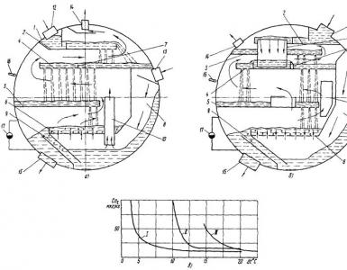
Rice. 3. Basic circuits for measuring the insulation of a three-winding transformer.

Rice. 4. Additional circuits for measuring the insulation of a three-winding transformer.
The insulation resistance of each winding of newly commissioned transformers and transformers that have undergone major repairs, reduced to the test temperature at which the initial values were determined, must be at least 50% of the initial values.
For transformers with voltage up to 35 kV inclusively with a power up to 10 MVA and arc-suppressing reactors, the insulation resistance of the windings must not be lower than the following values:
| Winding temperature, °C | 10 | 20 | 30 | 40 | 50 | 60 | 70 |
| R 60 , MΩ | 450 | 300 | 200 | 130 | 90 | 60 | 40 |
The insulation resistance of dry transformers at a winding temperature of 20-30°C should be for transformers with a rated voltage:
Measurement of dielectric loss tangent and capacitance
When carrying out tests using the Vector insulation parameter meter, one should be guided by the requirements of the Instructions for the technical operation of the mobile electrical laboratory LVI-3 (or ETL-35) and the instruction manual for the device.
The measurement of the dielectric loss tangent and the capacitance of power transformers is carried out at a voltage of 10 kV.
The dielectric loss tangent and the capacitance of the windings of power transformers are measured according to the schemes in Table. 3. In this case, the sequence of measurements is not standardized.
| Double winding transformers | Three winding transformers |
||
| The winding on which measurements are made | Grounded parts of the transformer | The winding on which measurements are made | Grounded parts of the transformer |
| HH | HV, tank | HH | CH, HV, tank |
| VN | NN, tank | CH | HH, HH, tank |
| (HV+LV) | Tank | VN | HH, CH, tank |
| (HV+SN) | NN, tank |
||
| (HV+SN+LV) | Tank |
||
If, according to the results of measurements according to the schemes of Table. 3, an overestimated value of tgd of one or more windings was revealed, a number of additional measurements are performed for individual sections (zones) of insulation, which makes it possible to identify a section with a reduced level of insulation according to the schemes of Table. 4.