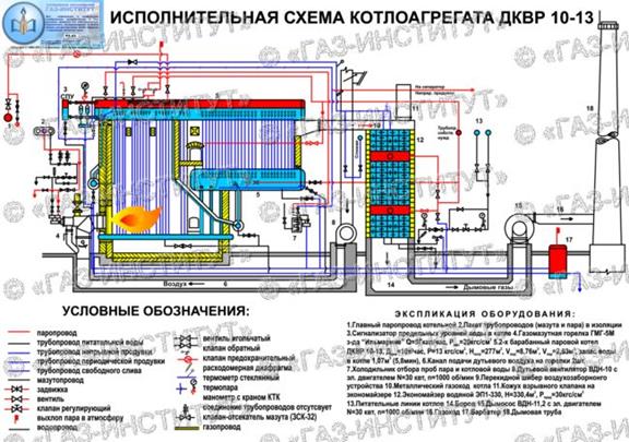
Boilers DKVR-10-13
Reconstructed double-drum vertical-water-tube boiler, steam boiler. With a capacity of 10 t / h, excess steam pressure of 1.3 MPa (13 kgf / cm 2. E-type boiler with natural water circulation.
The technical characteristics of boilers DKVR-10-13 are indicated earlier in the general technical characteristics of boilers of the DKVR type.
The steam boiler DKVR-10-13, in comparison with the designs of boilers DKVR with lower steam capacity, has the following differences:
In the DKVR 10-13 boiler, the lower drum is raised, under which access is made for the maintenance personnel;
The boiler has an additional front and rear screens, respectively, has a front and rear collectors;
The rear manifold is located under the front of the lower drum, from below;
The front collector is located on the front part of the front wall of the boiler, that is, it is removed from the furnace. Downcomer unheated pipes supplying water to the front collector from the upper drum are located in the lining.
The furnace of boilers DKVR-10-13 is screened from 4 sides with screen pipes;
In the convective bundle of DKVR-10-13 boilers, both partitions dividing the bundle into the 1st and 2nd gas ducts are made of heat-resistant cast iron.
Unlike boilers of lower productivity, the lower drum of the DKVR-10-13 boiler is raised, and access for maintenance personnel is provided under it. The drums are interconnected by pipes of the convective beam. Pipes are fastened to the drums by rolling to ensure the tightness of the connection between the pipe and the drum, without destroying the structure and without reducing the strength of the drum wall.
Each header and bottom drum of the boiler has intermittent blowdown piping with two valves (flange valves).
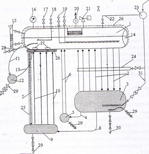
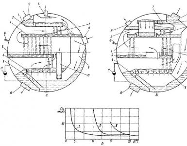
The main elements of the steam boiler DKVr-10-13
1. Top drum; 2 . Lowering and lifting pipes of the convective beam; 3 . lower drum; 4 . Bypass pipes (3 pcs.); 5 . Rear screen manifold; 6 . Rear screen pipes; 7 . Lowering (unheated) pipes; 8 . Bypass pipe side screen; 9 . Side screen collector; 10 . screen pipes;
11. Drop pipes of the front screen; 12 . Front collector; 13 . Lifting pipes of the front screen; 14 . Laz; 15 . Water level indicator (2 pcs.); 16 . boiler manometer; 17 . air vent; 18 . Input of chemicals (including cleaning chemicals); 19 . Feed water inlets (working and reserve);
20. Main steam stop valve or gate valve; 21 . Safety valves (spring valves - 2 pcs.); 22 . Steam pipeline for auxiliary needs of the boiler; 23 . General steam pipeline for own needs; 24 . Central blower; 25 . brickwork; 26 . Shotcrete; 27 . Easy-melting plugs); 28 . Continuous purge; 29 . Periodic purge; 30 . Pipeline for draining water from the boiler; 31 . Steam pipeline for supplying steam for heating the lower drum.
The furnace is completely screened, divided by a fireclay brick wall into the furnace itself and the afterburner. The afterburner reduces heat loss with flue gases and eliminates chemical. underburning, and also prevents the torch from being drawn into the convective beam. Between the first and second rows of the convective bundle, a fireclay partition is installed, which separates the convective gas duct from the afterburner.
A cast-iron baffle is installed in the convective flue, which organizes a horizontal turn of the flue gases, which contributes to a greater transfer of heat from the flue gases to the convective heating surfaces. The lining of the boiler is heavy. Two oil-gas burners "GMG" are installed from the front of the boiler. For blowing the tubes of the convective beam, a blower is installed on the rear wall of the boiler.
Boiler drums are made of low-carbon low-alloy steel grade 16 GS: - 0.16% carbon, manganese and silicon - less than one percent. Collectors are made with a diameter of -219 mm. Downcomer unheated pipes in the front part of the boiler - 179 mm, bypass pipes - 76 mm.
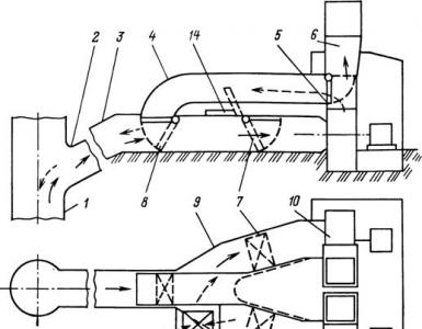
Scheme of the movement of flue gases in boilers DKVr - 10-13. The flue gases generated in the boiler furnace during the combustion of fuel give off part of the heat to the screen pipes, and through a specially made window located on the left side of the rear wall of the furnace, they enter the afterburner chamber. In the afterburner chamber, the flue gases move from right to left, go around the first baffle of the convective beam and enter the first gas duct of the convective beam.
In the first gas duct, the flue gases move from left to right, they wash the pipes in a transverse flow, give them their heat at a lower temperature and enter the second gas duct of the convective beam (see scheme 4 of the movement of flue gases). In the second flue of the convective beam, the flue gases move from right to left, wash the pipes in a transverse flow and, having given them their heat, exit the boiler with the calculated temperature through a window made in the upper left part of the back wall of the boiler. From the boiler flue gases are directed to the economizer through the flue.
To clean the outer surfaces of the pipes of the convective bundle from soot and other deposits when the boiler is operating on fuel oil, a special blowing device (stationary blowing device) is provided. Through the rear wall of the lining along the axes of the drums through the tubes of the convective beam, a rotating blowing tube (made of stainless steel) passes, having a number of holes with nozzles for steam to escape. The front end of the tube enters a sleeve welded to one of the central tubes of the second row of the convective bundle. Rotate the pipe manually using a flywheel and a steel chain. In addition, portable blowers are available.
The pipes of the convective beam are blown when the boiler is running on fuel oil with steam or air at a pressure of 0.7-1.0 MPa (7-10 kgf/cm).
Blowing is carried out at the time specified in the local regulations, as well as with an increase in the temperature of the flue gases.