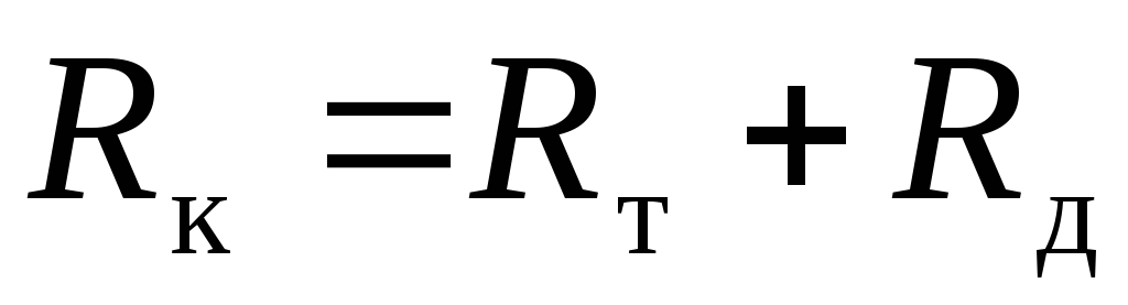
11 Calculation and selection of expansion joints
In thermal networks, stuffing box, U-shaped and bellows (wavy) expansion joints are widely used. The compensators must have sufficient compensating capacity to absorb the thermal expansion of the pipeline section between the fixed supports, while the maximum stresses in the radial compensators should not exceed the allowable ones (usually 110 MPa).
Thermal elongation of the design section of the pipeline , mm, determined by the formula
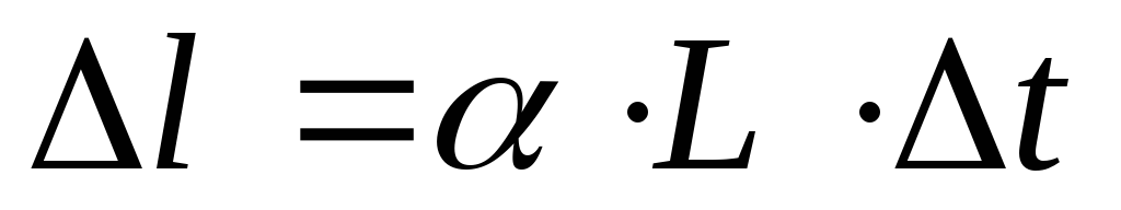 (81)
(81)
where  - average coefficient of linear expansion of steel,
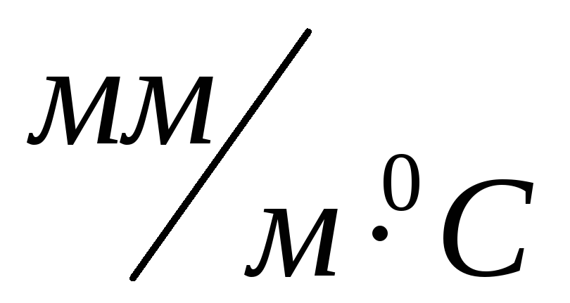
(for typical calculations, you can take 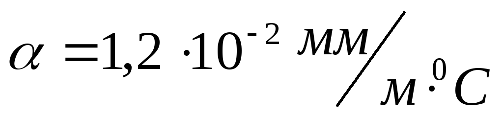 ),
),
 - estimated temperature difference, determined by the formula
 (82)
(82)
where  - design temperature of the coolant, o C;
 - estimated outdoor air temperature for heating design, o C;
L - distance between fixed supports, m (see Appendix No. 17).
The compensating capacity of stuffing box expansion joints is reduced by a margin of 50 mm.
Reaction of the stuffing box compensator- friction force in stuffing box packing  is determined by the formula
where  - operating pressure of the coolant, MPa;
 - length of the packing layer along the axis of the gland compensator, mm;
 - outer diameter of the branch pipe of the stuffing box compensator, m;
 - coefficient of friction of the packing against the metal, is taken equal to 0.15.
When selecting compensators, their compensating capacity and technical parameters can be determined according to the application.
Axial reaction of bellows expansion jointsis made up of two terms:
 (84)
(84)
where  - axial reaction caused by wave deformation, determined by the formula
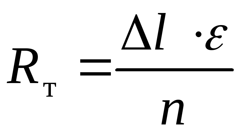 (85)
(85)
here l - temperature elongation of the pipeline section, m;
- wave stiffness, N/m, taken according to the compensator passport;
n is the number of waves (lenses).
 - axial reaction from internal pressure, determined by the formula
 (86)
(86)
here  - coefficient depending on the geometric dimensions and wall thickness of the wave, equal to an average of 0.5 - 0.6;
D and d are the outer and inner diameters of the waves, respectively, m;
 - excess pressure of the coolant, Pa.
When calculating self-compensation the main task is to determine the maximum stressat the base of the short arm of the turn angle of the track, which is determined for the turn angles of 90 ° along  formula
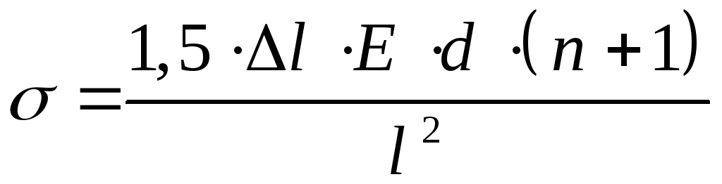 (87)
(87)
for angles greater than 90 o, i.e. 90+, according to the formula
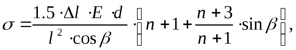 (88)
(88)
where l - elongation of the short arm, m;
l is the length of the short arm, m;
E - the modulus of longitudinal elasticity, equal to the average for steel 2 10 5 MPa;
d - outer diameter of the pipe, m;
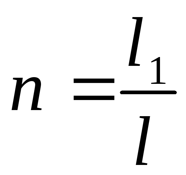 - the ratio of the length of the long arm to the length of the short arm.
When calculating angles for self-compensation, the value of the maximum stress should not exceed [] = 80 MPa.
When arranging fixed supports at the angles of rotation used for self-compensation, it must be taken into account that the sum of the lengths of the angle arms between the supports should not exceed 60% of the maximum distance for straight sections. It should also be taken into account that the maximum angle of rotation used for self-compensation should not exceed 130 °.